As with most electrical work, you should disconnect the negative battery cable. Since you will be disconnecting a number of connectors and working in tight areas, it is advisable to not ignore this step even though it may be possible to do the work without disconnecting the battery.
We start by removing the
intermediate steering shaft on the drivers side in the
engine compartment. To do this, you must remove the bolt
on the front of the shaft and the bolt/nut on the rear
end of the shaft (next to firewall). You only need to
turn the steering wheel about 90 degrees or less left/right
to gain access to these bolts/nuts. I found it easiest to
use a box wrench on the front (13mm) bolt with the bolt
head facing the passenger side of the car, and a long
extension (about 18 inches) and ratchet on the rear nut (15mm)
with the nut facing upward. Whatever mehods you use, make sure you note the position
of the shaft at all times so that
you can put it back exactly the same way! Also, I have
been told that you
should not turn the steering wheel more than 180 degrees
from center while disconnected from the shaft because
doing so can damage the air bag mechanism. Be careful when removing the intermediate
shaft because if you have the column lock bypass
installed, the steering wheel will turn freely once
either end of the shaft is disconnected! When the front
bolt is removed, the front of the shaft just slides off (to
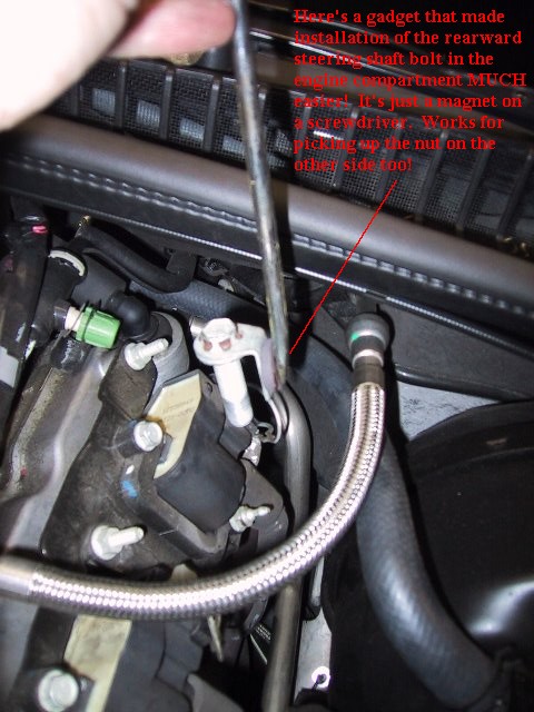
the side). When you remove the rear nut, the bolt may
fall out so be aware of where it is going if it falls out!
I found a magnet attached to the end of a screwdriver to
be the mechanics dream helper here! Removing this shaft
requires nothing more than removing the bolt in the front
and the nut/bolt in the rear; it's just a little tight to
work in there. Even with the bolt in the front and bolt/nut
in the rear removed, the shaft can still be in place and
used to turn the front wheels if you are careful and
don't let the front of the shaft fall off while you are
doing this. Remember that whenever you want to turn the
wheel, make sure the shaft is in place so that everything
stays in "sync"! When rotating the steering
wheel to access the nut/bolt on the ends of the shaft, I
found this technique of leaving the shaft in place the
best way to keep your rack, shaft and steering wheel all
aligned! Make sure you note the position of the shaft and
how it fits on both ends before removing anything and I
would recommend centering the steering wheel before final
removal of the shaft so that you'll know the orientation
of: (1) the rack, (2) the intermediate shaft and (3) the
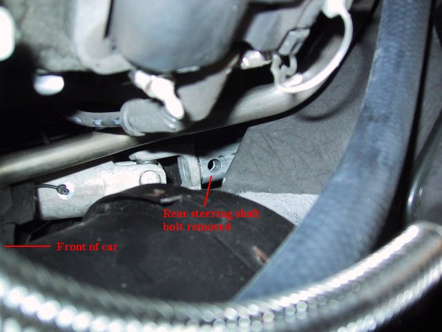
steering wheel. Once the front of the steering shaft is
dropped away, it just pulls out of the steering column in
the rear. Here's a shot of the rear (steering column)
side of the shaft under the hood with the bolt removed.
Now that the shaft is removed, the column is free to be pulled out from the inside of the car once you've removed the 4 13mm nuts holding it inside the car. I would recommend removing the rubber grommet against the firewall along with it's teflon insert. You can do that now or after you've pulled the column out from the inside. You can put some grease on around the teflon washer to eliminate any possible squeaks when you reinstall it later. I would recommend pulling the rubber gromet and teflon washer over the end of the shaft from the engine compartment now. You can put it back on once the column is back in the car later. Note the orientation of the teflon washer when you pull it from the shaft.
As with other work such as a column lock bypass, you need to remove the lower dash panel at the drivers knees. In addition, you also need to remove the other smaller panel between the front panel and the firewall. To remove the larger panel, you need to remove the two torx screws underneath along with the two to either side of the steering wheel (one is behind the trunk release which pops out and the other is behind the small vent to the left of the ignition key which also pops out). Once these 4 torx screws are removed, you can work the dash panel down and out. The left side may be a little more difficult to force out because you need to pull the top part out toward the driver since there are two clips behind this location. As for the panel underneath just above the feet, there are only three connectors holding it in. There are two plastic ribbed "push ins" toward the driver's seat and one metal "star clasp" that site on a small metal post toward the firewall. The metal clasp can be bent slightly with pliers and then rotated off. You can then flatten it back out to ready it for installation later.
Disconnect all the
electrical connectors that connect the steering wheel/signal
cluster to the rest of the car (5 of them if you don't
have a column lock bypass and 4 if you do have the CLB
installed). Disconnect the connector on the steering
sensor at the base of the steering column. Disconnect or
clip any zip ties that would prevent the steering wheel
and column to be pulled out freely (the tie holding the
steering sensor wire against the column and the bigger
harness holding the other connectors. A few minutes of
studying where all the connectors go and how they will
come out when the steering wheel and column are pulled
out will save time here later and will eliminate any
"fighting" with connectors as you are trying to
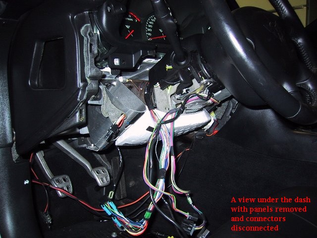
pull out the wheel/column. The following shows both dash
panels removed and all the connectors dangling free (top
photo below) and shows the sensor at the base of the
steering column with the connector already disconnected (bottom
photo below).
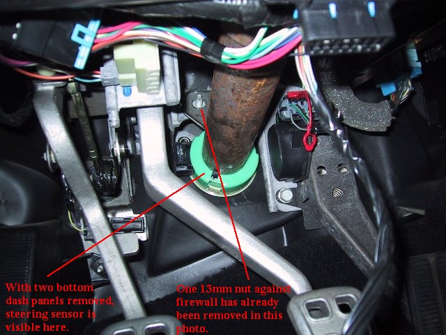
Now that the intermediate
shaft is removed in the engine compartment, there are
only 4 13mm nuts holding the steering wheel and column in
place. You can see one bolt in the picture above (the nut
has already been removed). There is one more on the
opposite side (right side in photo) of the steering
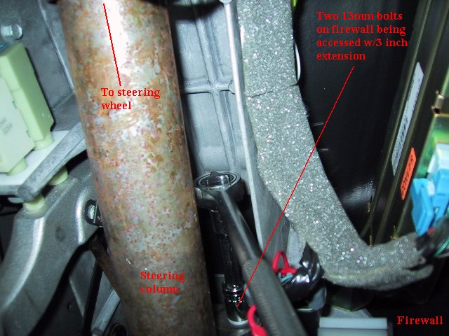
column that cannot be seen in the photo above. I found
that a small ratchet with a 3 inch extension worked well
in this tight area (see photo below).
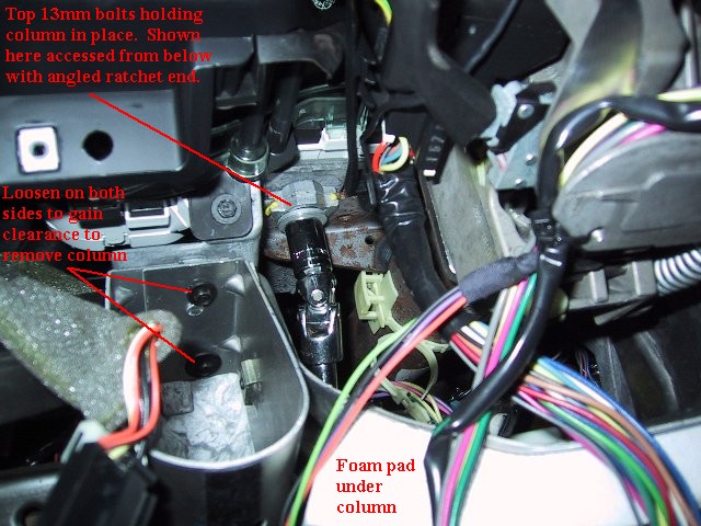
Now that the front two
nuts at the base of the column are off, you only need to
remove the top two nuts. Before doing this, I had to drop
the metal kick panel (the one with the large styrofoam
pad) a bit. You only need to loosen the 4 screws holding
this on so that it drops down a bit (see photo below);
you should not need to remove it entirely. If you do not
lower it, the assembly may not drop down low enough for
it to clear the 13mm bolts above that you just removed
the nuts from. Once the kick panel has been dropped a
bit, you can remove the two 13mm nuts holding the top of
the steering wheel/column assembly (also shown below).
Note that I removed the lower half of the black plastic
cover that the tilt lever goes through. I don't think you
need to remove this cover if you lower the kick panel
enough so that there is enough clearance.
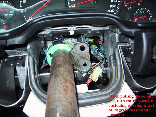
With both of the top 13mm
nuts removed and the kick panel lowered a bit, you can
gently lower the steering wheel/column assembly and pull
the entire wheel/column out toward the drivers seat. Note
again that as you pull it out, you should maintain the
steering wheel's position (centered) relative to the
column base. I have been told that turning the steering
wheel more than 180 degrees with if off the vehicle can
cause problems with the air bag system. This is
especially important if you have installed a column lock
bypass because your steering wheel will turn (very)
freely. To get enough clearance to get the steering
sensor out, you may have to rotate the entire assembly 90
degrees as shown below while pulling it through. There
should be little/no resistance when pulling the assembly
out so do not force anything. If it seems to be hanging
on something, look at the top 13mm bolts where you
removed those nuts. It's probably hanging up there and
you may have to drop the kick panel a little lower.
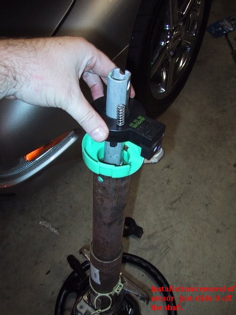
Remembering to keep the
wheel centered, you can set the steering wheel on the
floor with the base of the column up toward the ceiling.
Then simply pop off the tan colored dust cover at the
base of the column by popping the three prongs away as
you remove it. The sensor will simply pull right off the
shaft. Clean the shaft with a towel that has a light mist
of WD-40 on it. Once the shaft is clean, you can put the
new sensor onto the shaft in the same orientation as the
old one when it came off. The picture below shows the new
sensor going on. Note that the spring/pin that holds the
sensor in a centered position is still in place. If
you've kept your steering wheel centered, you'll notice
that the sensor will fit right on the shaft in the proper
orientation without removing the centering pin. Once the
new sensor is seated in the green "cup", you
can remove the centering pin from the new sensor (centering
pin seen below as a spring/pin).
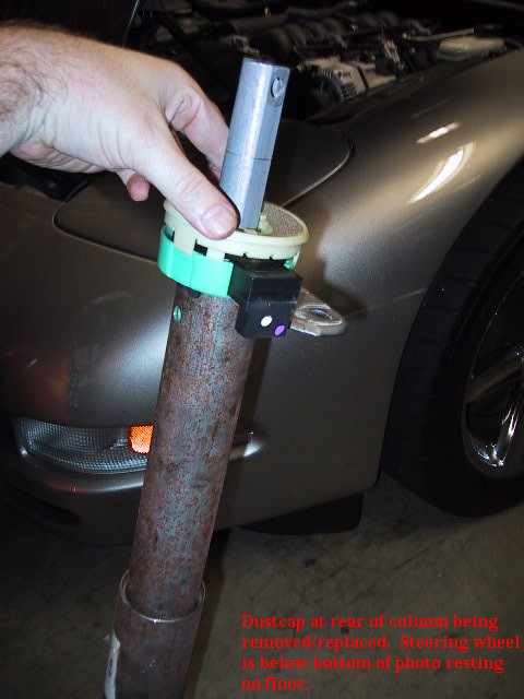
Remember to put the dust
cap back on after the new sensor is in place.
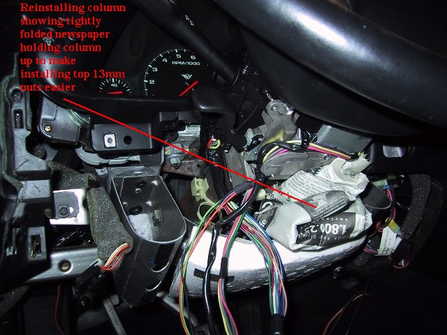
You are now ready to
reverse the procedure for the installation. When you put
the steering assembly back in the car, it may help to
place some tightly folded newspaper between the column
and the kick panel as shown below so that the top of the
column is held upward. This will facilitate getting the
top nuts back on. You can see that the left upper
nut is already in place (this nut is intersected by the
red pointer line about in the middle of the line).
Note that the steering wheel should still
be centered and so should the rack because when you
removed the intermediate steering shaft in the engine
compartment, you had everything centered. So, when
installing the intermediate shaft, everything should line
up! Remember the trick with the magnet on the screwdriver
too! It really helps to get the rear bolt in the hole (pic
below).
Once everything is reassembled and the battery reconnected, stand close to the vehicle and hold the lock and unlock buttons on your remote simultaneously to resynchronize your remote with the car. Also, make sure to clear any codes by holding "Options" and pressing "Fuel" 4 times in a row, then waiting for "Manual Diagnostics" and holding the reset button to clear codes for all the different systems. The "Options" and "Trip" buttons can be used to scroll through systems.