Profile Prism
Procedure for profiling a printer
Topics of Interest
General
Using Profile Prism Software
Quick start instructions for profiling a
printer:
Note that scanning and printing software
varies greatly from one manufacturer to another. While the
quick start instructions below describe the overall process
of creating a printer profile along with some recommended
settings, we recommend reading and being familiar with the
detailed instructions in the following section as well.
- Open the (ICC aware) software you
intend to use to print photos.
- Open the print driver properties and
select appropriate paper type.
- Set print driver
settings according to recommendations.
- Turn off all color management/printer
ICC profiles.
- Print the "printer-target-40.tif"
file at its original size (approx. 7.92 x 5.77 inches),
or
- If profiling an older model Epson printer in
"no color adjustment" mode, you can use use "printer-target-bright.tif"
- Allow to dry/cure 12 hours.
- Cut printed target at dotted line.
This leaves about about 1/8 inch black border around
the printed color patches.
- Place both the IT8 reference target
and the printed target on scanner glass.
- Place piece of black construction
paper on top.
- Close scanner lid.
- Open scanning software set software
settings as recommended here.
- Scan the targets and make sure targets
are not rotated in the scanned image.
- Open Profile Prism and set "Type
of Device to Profile" to "Printer".
- Bring image into Profile Prism and
place four corner markers on IT8 ref.
- Evaluate the messages to determine
exposure, clipping, etc.
- Click "Printer Target" radio
button on top of window.
- Place four corner markers on printer
target.
- Evaluate the messages to determine
exposure, clipping, etc.
- After placing all eight corner markers,
set PP options as follows:
- Type of device to profile:
already set to printer
- Reference target:
same as that shown on lower/right of ref.
target
- Printer target:
select the target printed in step 5 and 6
above
- Profile description:
printer model, paper, and other info as
desired
- File name: click
"..." and select a name for the ICC
profile
- Profile for: highest
accuracy
- White balance: N/A
- Tone reprod. curves:
N/A
- Initial adjustments:
all "normal" or zero
- Click "Create Profile"
Note: Once the profile is created, you must
use the same print driver and software settings selected in
steps 2-3 above. To utilize the profile, simply select the
profile as the "Printer ICC" or "Print Space"
in the printing software.
The following describes the process for
creating an ICC profile for a printer using Profile Prism:
I.
Printing the Printer Target and Scanning the Result
Before we use the software to create a
printer ICC profile, we must use our photo printing software
to print a copy of the included "printer-target-40.tif"
file. We will print this printer target at its original size
(about 7.92 x 5.77 inches) and use our scanner to scan the
print that the printer generated and the IT8 reference target
at the same time.
- Software/print driver
preparation: Profile Prism does not provide
a facility for printing the printer target because
the printer target should be printed through the
software that you use to print images, i.e., the
software that will be utilizing the printer ICC
profile once it is developed. For example, if you use
Qimage, print the "printer-target-40.tif"
file with Qimage using the same program and print
driver settings that will be used later (with the
profile). Before printing the printer target, open
Qimage (or other ICC aware software) and follow the
checklist below:
- Make sure that all print
quality options in your printing software are
set to the same settings that will be used
when printing your normal prints. Remember
that profiles only work when printing "conditions"
are exactly the same as they were when the
profile was created (with the exception of
the profile itself being in place).
- If the
software you are using offers any final print
sharpening, turn that option off (even if you
normally use it). Extra sharpening is not
needed and in cases where target alignment is
not perfect, sharpened edges can cause false
color readings. As an example of how to
disable this feature in Qimage, click "Prints",
"Print Interpolation" and move the
final print sharpening slider all the way to
the left. Just remember to go back to that
window and click "Restore Defaults"
before printing your normal photos.
- Click "File", "Printer
Setup" and set all print driver
properties as appropriate for the paper and
type of printing you are doing. Remember that
the print driver properties used when
creating the profile must match exactly to
the properties used when you later utilize
that profile. For recommended driver settings,
click
here. Be sure to
make selections that are appropriate for the
paper you are using and most importantly,
confirm that the paper you are using is
compatible with your printer! Some third
party papers or papers from different
manufacturers may not work properly and may
make profiling difficult/impossible. Also,
turn off all photo enhancing effects or other
options labeled "automatic".
Options like "photoenhance" or
"auto contrast" will not work with
ICC profiles because they do not produce
stable (static) results from print to print.
- Because we want to print raw
data for the purpose of deriving a profile,
make sure that your printing software is NOT
utilizing an ICC profile for the printer. In
Qimage, this only involves changing "Printer
ICC" to OFF. This option is located on
the lower right of the main window in Qimage.
If using a photo editor, click "File",
"Printer Setup" or "File",
"Print Options" and look through
all advanced settings to ensure that no ICC
profile or "print space" is
associated with the printer. For example, in
PhotoShop 6 or 7, click "File",
"Print Options", and check "More
Options" and drop down and select "Color
Management". Then make sure that "Print
Space" is set to "Same as Source".
- Printer preparation: Make
sure that you have the appropriate media/paper in the
printer (the same media that you selected in the
print driver above). Also, if your printer offers a
utility for checking the print head nozzles,
performing that test is highly recommended prior to
printing the printer target. Clogged print nozzles
can cause the generated profile to be inaccurate and
performing a nozzle/print head check prior to
printing can eliminate profile problems. If clogged
nozzles are found, they MUST be cleaned prior to
printing to ensure that all print head nozzles are
operational.
- Printing the printer target:
Now that we have selected the proper print settings
for both the software and print driver and ensured
that the printer is in good operating condition, we
must print the file called "printer-target-40.tif"
located in your Profile Prism folder (normally \program
files\prism). In Qimage, this is accomplished by
making sure that the "Image Fitting" crop
button (scissors icon above the thumbnails) is up/not
depressed, highlighting the "printer-target-40.tif"
thumbnail from the \program files\prism folder,
clicking "Custom", "Original Size",
and then printing. Note that if you use a photo
editor instead of Qimage to print the printer target,
the default print size of "printer-target-40.tif"
will be 7.92 x 5.77 inches. This size is fine and you
should not alter the size or resample the image.
Simply load the image and print the printer target at
its default size. IMPORTANT: If you are using an ICC
aware photo editor, you may be asked about color
management when you open "printer-target-40.tif".
If so, make sure that you do NOT color manage the
image; select "Do not color manage" or
"Leave as is". Once you have printed the
color target, refer to the information below.
Evaluating your printed target: We recommend letting your test print of
the color target dry/set for at least one hour, but
ideally overnight. Nearly all inkjet printers produce
prints that are dry to the touch immediately, however,
many papers/inks take at least an hour for the final
color to "set". During this time, there are
often noticeable color shifts in the print, so you
always want to make sure the printed color target
contains "final color" before profiling.
Cutting out
your printed target: Once the
print has dried, use a paper cutter or razor knife/straight-edge
to cut the printed target from the page. After
cutting at the dotted line, you should be left with
your printer target surrounded by about a 1/8 inch
black border. Use of a rotary paper cutter is
recommended because edges that are straight and
"true" will make scanning and alignment
easier.
Note about
targets from older versions:
Printer targets from old versions of Profile Prism
must not be used. If you have targets/scans from
versions prior to v4.0, they will not work and new
printer targets will have to be printed using the
included printer-target-40.tif file.
Printing the
printer target at a different size: If your printer/paper is not able to
accommodate the full 7.92 x 5.77 inch printer target,
you may print the target at a smaller size. The
larger the printed target the better, since the color
patches are very small on the 9,261 patch printer
target, but if your printer cannot accommodate the
recommended (original) size, simply print the target
as large as you can given the limitations of your
printer/paper. If you must print the target smaller
than about 5x7 inches, increase your scan resolution
to 400 PPI when scanning to accommodate the smaller
printed target.
Using the bright target:
If you are profiling a printer that has very dark
output (such as Epson printers in "no color
adjustment" mode), we recommend using the
optional "printer-target-bright.tif"
instead of the normal "printer-target-40.tif".
The "printer-target-bright.tif" is a
brighter target that is more suited to print driver
settings that produce dark output. Since Epson
printers running in "no color adjustment"
mode are the only combination that produces output
that is heavily weighted to the shadows, do not use
the bright target on non-Epson printers or Epson
printers running in sRGB or "color controls"
mode unless you have reason to believe that the
output from your printer is darker than normal.
IMPORTANT: If you do use the bright target, remember
to set the "Printer Target" parameter to
"printer-target-bright.tif" prior to
clicking the "Create Profile" button so
that Profile Prism knows which printer target it is
working with.
- Scanning
your printed target: Place the targets on
the glass of your scanner against the edge of the
scanner glass for easy alignment. Place the IT8
reference target on the top and your printed target
underneath with the bottom edge of the IT8 target
touching the top edge of the printed target as shown
below. Since the quality of your printer
profile will be directly related to the quality of
the scan, click here to see the recommended scanner
settings by manufacturer. Once you have
set your scanning software accordingly, scan the two
targets. The resulting scan should look something
like this.
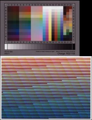
Note that your IT8 reference target that you received
when you purchased Profile Prism is on the top and
your printer target (labeled "printer-target-40"
in the lower right) is on the bottom. Also note that
it really doesn't matter which target is on the top/bottom.
The above layout is used for simplicity. It is also
not important that the two targets be aligned left-to-right
or that the two targets are exactly the same size;
the only thing that is important is that neither
target appears rotated.
Important: See the importance of a good scan below for information
on how to get a high quality scan and how to evaluate
your scan to determine if it is acceptable for
creating a printer profile.
Summary:
Using the instructions above, we have
used our photo printing software to print a file called
"printer-target-40.tif" from our \program files\prism
folder. We then scanned this printout along with the IT8
reference target that we received when we purchased
Profile Prism. Profile Prism software will now be used to
create a printer ICC profile. An accurate printer profile
can be generated as long as both the printer target and
IT8 target are scanned in the same scan, and that scan is
of acceptable quality.
II. Using the Software
Step 1: Specify profile
details
Before telling Profile Prism to generate
your ICC profile, you need to specify a name, description and
some options. Below is a description of each entry. If you
are creating your first printer profile, you need only
concern yourself with the underlined entries.
- Type of Device to Profile:
Since we are profiling a printer, select "Printer"
for this setting.
- Profile Description:
Enter a description for the profile such as "Acme
800 printer profile - matte paper". If you leave
this entry blank, it is possible that your ICC aware
software may not be able to find the profile later.
- File Name: To
save your profile to the system color folder (c:\windows\system\color
for example), click the "..." browse button
and enter a new file name in the "Save As"
dialog or select an existing profile to overwrite.
You may also type a file name directly into the edit
box if you like, however, if a file name is typed
without specifying a path, the profile will be saved
in the folder where Profile Prism is installed. For
example, entering "test" in the file name
field will result in a profile named "test.icm"
being stored in your \program files\prism folder.
- Reference Target:
This reference file identifies the actual color for
all color patches on your IT8 color target and is how
Profile Prism knows the actual colors on your target.
Simply look at the name of the data file listed here
and make sure that the same name/number is listed on
your reference target in the lower right corner. Note
that the target "version" is sometimes
referred to as the target "charge". If the
version/charge listed in the dropdown does not match
the version/charge listed in the lower right of the
reference target, select the proper file name that
matches. Once you have verified this entry, it is not
necessary to change it unless you start using a
different paper target that has a different version
number stamped in the lower right corner.
- Printer Target:
Refers to the color target printed in the "Printing
the printer target" section. Select the target
that you printed and then scanned: either "printer-target-40.tif"
or "printer-target-bright.tif".
- Profile For: If the
default "Highest Accuracy" is selected,
Profile Prism will generate a printer profile that
produces the most pleasing colors by compensating for
perceptual differences of in-gamut and out-of-gamut
colors, expanding the effective range of colors that
are difficult to reproduce on printers such as bright
blues and reds. If "Smoother Gradients" is
selected, the printer profile will produce more
"mathematically" accurate colors with
smoother gradients, however as a compromise, some
colors such as bright blues and reds may appear
slightly shifted in hue.
- Tone Reproduction Curve:
This option is disabled for printer profiling.
- White Balance: This
option is disabled for printer profiling. White
balance is determined by the "white" of the
paper you are using.
- Brightness: Choose
the "Normal" setting if you would like your
profiled images to have an ideal tone curve (100%
accurate brightness). Set this parameter to a
positive value if you would like to increase
brightness and shadow detail, and a negative value if
you would like your profile to render images with
darker shadows and an overall darker appearance. Note
that the brightness here actually operates on a gamma
curve, so a more accurate name for this parameter
would be "gamma". The term "Brightness"
is used simply so that it is a more recognizable and
less confusing term.
- Contrast: Choose the
"Normal" setting if you would like your
profiled prints to have an ideal tone curve (100%
accurate contrast). Set this parameter to a positive
value if you would like your profile to render prints
with higher contrast, and a negative value if you
would like your profile to render prints with less
contrast. Although the "Normal" setting
will ensure accurate contrast in the profile, some
photographers may prefer higher contrast results to
add more "pop" to prints and increase
separation between foreground and background. Most
digital cameras and film processors deliver pictures
with higher than normal/accurate contrast. Higher
contrast tends to hide noise in the shadows and give
a more "intense" or "sharper"
feel to prints, however, it also tends to destroy
some amount of shadow detail. Since anything other
than the "Normal" setting is considered an
"effect" or "enhancement", the
other values are available purely as a personal
preference since many people prefer more contrast
than provided by a totally accurate tone curve. The
"Normal" setting also provides the greatest
possible detail in the print, so if your normal
workflow includes any type of post processing using a
photo editor, it may be best to use the "Normal"
contrast setting since this will ensure that the
print has maximum detail.
- Saturation: Choose
the "Normal" setting if you would like your
profiled prints to have ideal saturation. Set this
parameter to a positive value if you would like your
profile to render prints with more saturation, and a
negative value if you would like your profile to
render prints with less saturation.
- Bias Settings: The
red, green, and blue bias values may be used to
control unwanted color casts or to introduce
different coloring effects. For example, if the
profile produces a noticeable yellow cast, setting
the red and green bias settings to negative values
will reduce yellow in the profile. Bias changes can
be made to the entire profile (if "bias includes
grays" is checked) or only to non-neutral colors
(if "bias includes grays" is not checked).
Cameras can suffer from hue shifts when shooting
under different light sources, while digital prints
can be affected by metamerism (prints having a
different appearance under different light), paper
brighteners, and other issues. These are just a few
examples where bias settings can come in handy by
allowing manual "tweaks" when necessary.
Note: always create profiles with bias settings at
zero and only change the color bias in your profile
if you deem it necessary.
- Metamerism Compensation:
Leave at the left (default) position if the printed
target reacts similarly to the reference target under
the scanner's light source. Move to the right to
equalize differences in metamerism (color shifts)
between the reference target and printer target. See Metamerism and
Printer Profile Accuracy
below for details.
Step 2: Open and crop the
image of the color target
- Click "File", "Open
Image" and browse to the folder that contains
the scanned targets. Select one of the images and it
will appear in the image crop area in the upper right
of the window.

- Next, locate the
upper/left edge of the IT8 reference target in your
image. To do this, use the horizontal/vertical scroll
bars on the bottom or right of the image to scroll,
or simply click on the image in the window and drag
it left/right/up/down using the hand.
- Next, click the upper left crop corner
button.

- Your mouse cursor will now change to
an upper-left box corner when you move the cursor
into the image area. Move this corner to the very
edge of the target, placing it at the upper left edge
of the black rectangle that surrounds the row/column
labels as shown below. The corner marker is shown
below as a black/white dashed line.
- Once positioned here, left click to
place the corner mark. You will notice a red corner
mark on the target image. If the corner mark is not
exactly on the outside edge of the black corner as
shown, simply repeat steps 3 and 4 until placed
properly.
- Repeat steps 3 through 5, locating the
other three corners of the target and placing their
corner marks appropriately. Note that the top two
corner markers should be placed at the edge of the
outer/black rectangle surrounding the text row/column
labels and the bottom two corner markers should be
placed below the gray scale.
Properly placed corner markers are shown below:
- Once all four corners of the reference
target have been identified, the four "corner
buttons" will only appear when you hover over
them with the mouse. When all four corner buttons are
"deactivated" and your target evaluation
messages appear in the "Messages" area, you'll
know that you have finished the cropping step. In
addition, Profile Prism will overlay white "punchouts"
on each color patch to verify alignment. The white
punchouts should appear within each individual color
patch on the target.
Note
regarding the "Jiggle corners" option: If
the "Jiggle corners" option above the image
is checked, Profile Prism will "jiggle" all
four corner markers to try to obtain the most
accurate target alignment. Note that this option may
move the red corner markers so that they no longer
align perfectly with the edges of the target. This is
normal since obtaining the best overall/average
alignment of the white punchouts may require moving
some/all corner markers slightly. To place the
corners manually without Profile Prism moving them,
simply uncheck the "Jiggle corners" box and
place the four corner markers again.
- Simply move
around the target and make sure that proper alignment
exists by ensuring that each individual color patch
contains a white punchout and that none of the white
punchouts appear to overlap into neighboring color
patches.
- Now we mark the
four corners of the printer target (the target on the
bottom of the scanned image). Check the radio button
for "Printer target" above the scanned
image and repeat steps 3-8, marking the four corners
of the printer target as shown below. Note that since
the printer target contains very small color patches,
alignment is critical, so be sure to place the crop
markers as close to the corners as possible. Notice
that we are cropping at the tiny red corner markers
at the edge of the color patches and not
at the dotted line where we cut the target from the
page. It also helps to have "jiggle corners"
checked so that Profile Prism can assist you in fine
tuning the alignment.
 upper left
crop corner
upper left
crop corner
 upper right
crop corner
upper right
crop corner
 lower left
crop corner
lower left
crop corner
 lower right
crop corner
lower right
crop corner
- Once the fourth
corner of the printer target is marked, Profile Prism
will display white "punchouts" for each
color patch. Since the printer target contains so
many small color patches, lighting variance is not
accounted for on the printer target. Simply make sure
that the white punchouts appear wholly contained
within the color patches.
- After locating the fourth corner of
both targets, messages will appear in the messages
box. For printer profiling, the most important
messages are those regarding "clipping". If
many patches are clipped, you may need to modify your
scanner settings and rescan the targets with settings
that don't cause clipping. While a few patches will
always be marked as min/max with "X"
markers, strive to get a scan that has less than 10
"X" markers on each target. Generally, the
less "X" markers, the better the profile.
Notes on Profile Prism feedback
and messages:
Histogram: The
histogram that displays in the lower left corner of the
window after cropping a target can provide useful
information about the capture of your color target. The
histogram shows the distribution of pixel brightness
values from left (black) to right (maximum brightness).
The higher the curve, the more pixels contain that level
of brightness. Ideally, brightness should be distributed
from left to right on the graph with no large "clumps"
of data on the left or right. A large spike on the left
of the histogram indicates that some shadow detail on the
target was clipped (not visible because it is completely
black or zero in one or more RGB color channels). A large
spike on the right side of the histogram indicates that
some highlight detail on the target was clipped (not
visible because it is completely white or maximum in one
or more RGB color channels). Depending on the device
being profiled, it may be impossible to achieve an "ideal"
histogram where brightness is distributed throughout the
entire 0-255 data range, but try to minimize "clumping"
of data on the left/right as much as possible. Below are
some examples of "good" and "bad"
histograms.
Good histograms:
The above shows a typical histogram of the IT8 target (on
the left) and a typical histogram for a printer target (on
the right). The red endpoint markers on the left/right
are very short, indicating that only a very small amount
of data is at minimum/maximum brightness.
Bad histograms:
The above histograms show data that is not uniformly
distributed indicating improper exposure of the image.
The graph on the left, although it certainly captures the
entire range of brightness values in the image, is
underexposed. With the histogram compressed into the
lower portion of the graph, less data range is available
for profiling and the resulting profile may not be as
accurate as it could be if the brightness values were
more evenly distributed. The image that generated the
left histogram above will look dark and dull.
The histogram in the middle shows two problems. First,
the red line on the right (although relatively short),
indicates that some pixels in the image were at their
maximum brightness (255). Also, notice how the data doesn't
start until about 1/3 from the left. This indicates that
there are no dark pixels in the image which compresses
the capture range and makes black look gray. The image
that generated this histogram will appear with a "haze"
since contrast is lowered by the absence of true blacks
and dark colors.
Finally, the histogram on the right shows a very large
red (maximum) indicator on the right, indicating that
many pixels were at their maximum brightness. This image
is very overexposed and will not profile accurately. In
addition, the histogram on the right also shows a red
spike on the left indicating that some pixels were at
zero (minimum) which can indicate loss of shadow detail.
The image that generated the right histogram above will
look super bright and oversaturated as well as being very
contrasty. Unfortunately, images like this are what many
scanners capture when set at their default values. Such
images will have very vibrant color and a high level of
"pop", but are far from realistic and
will not profile well because much of the color target (in
the shadows and highlights) cannot be captured due to
data/pixels being "off the scale" by being too
dark or too bright.
When possible, all of the above conditions should be
avoided/minimized by tweaking the scanning software
controls if possible. The problem must be corrected up
front (at scan time) and must not be corrected with photo
editors after the fact since this cannot bring back
clipped data that was lost due to an overexposed scan.
Overexposure or clipping can normally be addressed by
setting "shadow" to zero, "highlight"
to 255, and gamma to 1.0 in your scanning software. If
the white patch in the lower left of your targets is not
clipped, but there is still a red line on the right of
your histogram indicating some values at maximum (255),
it is possible that the scanner is oversaturating. In
that case, reducing saturation by 25% normally will bring
the saturation into range and prevent the saturation
clipping.
Pixels at min/max brightness and clipping:
Pixels at min/max brightness: When
Profile Prism examines an image of a color target, it
will determine the range of brightness values captured in
the target; that is, the darkest and brightest pixel
values found on the image of the target. Due to
limitations of the capture device or simply due to the
brightness range found on the color target, these minimum/maximum
values need not always be 0 and 255. An image of a color
target, for example, may range from 4-251, meaning that
the darkest pixels found were a brightness of 4 and the
brightest were 251. Profile Prism will report the number
of color patches that contained at least some pixels that
were at minimum or maximum brightness. Obviously, there
must always be a darkest and brightest patch on the color
target, so at least two patches will always be reported
as containing these darkest/brightest pixels. If a large
number of color patches are marked as containing the
darkest or brightest possible values however, it may
indicate a problem. The message displayed will start with
"Note:" if there are less than ten color
patches containing min/max brightness and "WARNING:"
if there are ten or more color patches that contain
pixels at min/max brightness. A large number of patches
that contain min/max brightness could indicate that the
device that captured the image of the target simply
"ran out of room" and bottomed/topped out. In a
case where many color patches contained pixels of min/max
brightness, since many pixels were found at min/max
brightness, it is likely that at least some of them could
not be properly recorded and the actual value
could not be determined. Some things that can cause such
a "truncated" range include: overexposure,
oversaturation, inappropriate gamma setting, etc. If you
get 10 or more patches at min/max brightness, try
changing the exposure (shadow and highlight values on a
scanner for example), the saturation setting, or the
gamma setting to see if it brings more patches into range.
Clipping: In contrast to color patches
that contain some bottomed/topped out pixels, clipping
can occur in more extreme cases. Clipping is a condition
where all pixels in a measured color patch are at their
min/max value or there was some anomaly in the
measurement that indicates that the values in those
patches cannot be depended upon to be accurate. There are
three conditions that can cause clipping: (1) every pixel
measured in the color patch was at min/max value, (2) no
incidental variation (noise) was found in pixels: they
were all measured at exactly the same value, or (3) no
difference was found between two consecutive color
patches. Any of these three conditions normally indicates
that the value measured is probably not accurate. Once
again, try altering exposure, saturation, or gamma
settings to compensate. The number of clipped patches (marked
with a black "X" marker) should be minimized
since this indicates that the entire target could not be
captured and may result in less accurate profiles.
"X" markers and what they mean:
Green
"X": A green
"X" indicates that some pixels were at the
minimum value (shadow threshold). Since some pixels were
at minimum value and some were not, this often indicates
that the color patches in question are simply the darkest
measured patches on the target. If only a few patches
contain green "X" markers, no problem is
indicated. If a large number of green "X"
markers appear however, it could mean that the color is
at or near the minimum brightness value detectible by the
device. In the case of many green "X" markers,
your capture device may simply not be detecting dark
colors reliably and this could be an indication of
underexposure, inappropriate gamma setting, or simply a
limitation of the device being able to capture darker
colors.
Red
"X": A red
"X" indicates that some pixels were at the
maximum value (highlight threshold). Since some pixels
were at maximum value and some were not, this often
indicates that the color patches in question are simply
the brightest measured patches on the target. If only a
few patches contain red "X" markers, no problem
is indicated. If a large number of red "X"
markers appear however, it could mean that the color is
at or near the maximum brightness value detectible by the
device. In the case of many red "X" markers,
your capture device may simply not be detecting bright
colors reliably and this could be an indication of
overexposure or oversaturation.
Black
"X": A black
"X" on a color patch indicates that the color
patch was clipped. This condition is worse than pixels
being at min/max value since it indicates a problem where
inaccurate capture of the color patch is nearly
guaranteed. See "Clipping" above.
Scrolling through clipped patches: To
locate and scroll through the clipped patches on the
target to view them, simply click on the "WARNING/Note:
n patches are at minimum/maximum value..." message
in the message box on the bottom of the window. Each time
you click on the message, Profile Prism will move to the
next clipped patch on the target.
Densitometer: To further assist with
evaluating the colors in your captured target image,
Profile Prism offers a densitometer that can be used to
view the measurements for each color patch. After all
four crop corners have been placed on a target image, you
can point to any color patch on that target and right
click to see Profile Prism's evaluation of that color
patch. You will be able to view the original measured
color of the patch, the lighting variance, and the
corrected color after considering lighting variance.
Using the densitometer, you can determine which color
channel is clipping (if clipping occurred), the exact
color that was measured, how much lighting variation was
found at that color patch, etc. Note that when examining
color patches that are clipped with a black/green "X"
marker, you will rarely see RGB values at their minimum/maximum
value because you are viewing the RGB average over many
pixels. Only some pixels were found to be clipped, so the
average measured values will not normally show clipping.
Step 3: Generate the
profile
Now it's time to sit back and let Profile
Prism do its number crunching.
- Click the "Create Profile"
button in the lower left corner.

- Note that Profile Prism will be
performing billions of mathematical operations in the
process of creating your profile, so it may take
several minutes to generate a profile. You may follow
progress by observing the progress bar at the bottom
of the window.
- Note that once profile generation is
complete, the location of your new profile is visible
on the status bar at the bottom of the window.
- Make a final
review of the messages displayed in the "Messages"
box. Were any messages added? Profile Prism will add
messages as the profile is being generated. These
messages are:
- Printer/paper/ink dynamic
range: This message gives you an
indication of the dynamic range (contrast)
available on the media you are profiling. The
number displayed is the ISO brightness difference
between white (paper with no ink) and black (100%
black as rendered by your printer). The higher
the number, the more dynamic range (contrast) the
paper can handle. Colors will generally be more
vibrant on papers with higher dynamic range.
- Printer/paper/ink coverage
of Lab space: This message gives you an
indication of the size of the color gamut on the
media being profiled. The number displayed is the
percentage of the full Lab color space that can
be rendered by your printer on the media being
profiled. The larger the number, the more colors
your printer can reproduce on that paper, i.e.
the larger the color gamut. The lower the number,
the more compromises have to be made due to a
more limited color range. Note that Lab color
space is very large;
even larger than the color gamut of the human eye.
As a point of reference, sRGB color space (the
standard PC/web display color space) only covers
about 20% of Lab color space, so don't expect
much more than about 15% to 20% coverage from
your printer. Also keep in mind that this message
does not indicate where
the weaknesses in the color gamut occur, only the
overall size of the gamut. 20% coverage from a
printer does not mean that the printer can render
the entire sRGB color space for example, since
sRGB and your printer will cover a different
portion of the color gamut (different set of
colors) causing weaknesses in different colors.
- Printer profile usable
range: This message gives you an
indication of the range of values available to
the printer profile. The ranges for the red,
green, and blue channels are displayed separately
and refer to the values that were discernable in
the scan. A range of 0-255 indicates that there
was a detectable difference over the entire range
of printed values. A narrow range such as 64-255
indicates that there was no detectable difference
in printed values from 0-63, meaning that the
darker values in the range all looked "black"
(at least to the scanner). Ranges such as 0-255
up to 26-255 should be considered typical. Ranges
narrower than 26-255 could indicate that your
printed output is too dark for the scanner to
read or that shadows are blocked. Recheck the
settings that you used for printing your printer
target and try to decrease ink density or use
other print driver controls to print a brighter
and more uniform target. Printing a target on an
Epson printer with the driver set to "no
color adjustment" can often produce a print
that is too dark for typical scanners to read
accurately. See the section on print driver
settings to correct
this condition.
- Smoothing required:
Profile Prism actually tests your printer profile
after it is created to determine if posterization
(banding) exists due to abrupt shifts in color
gradients. After examining the profile, adequate
smoothing is applied to the profile to eliminate
posterization artifacts. The "smoothing
required" message indicates the level of
smoothing that was required to achieve smooth
gradients in the profile. Profile Prism always
performs a single pass to ensure smooth
transitions, so the minimum is 1 pass. If
posterization (banding) is still detected after a
single smoothing operation, more passes will be
performed until the posterization artifacts are
minimized. The more passes required, the harder
Profile Prism is working to correct deficiencies
in the print/scan. Normal smoothing requires
between 1 and 4 passes. If more than about 4
passes are required, it may be time to examine
your print settings (paper type, color mode, etc.)
to ensure that ink delivery is appropriate for
the paper you are using and/or examine the scan
settings to ensure that you are getting enough
detail in the scan in the shadows and highlights.
The most common causes of needing extra gamut
smoothing are: (1) the scanner is not picking up
reliable data in the shadows; try different scan
settings and/or (2) a paper type was selected in
the print driver that applies either too much or
not enough ink; experiment with different paper
types.
- WARNING - color patches
detected out of correction range: Like
an evaluation of "Fail" in the spectral
sample range, this warning message is very rare
and will normally not appear. It indicates that
Profile Prism found color patches on the target
that are so far off that it could not correct
those colors completely. While some color patches
may not be 100% accurate in the profiled image if
this message appears, it doesn't mean that the
error will be visible. In fact, the profiled
colors will always be more accurate than
the original. This message simply means that
Profile Prism was only able to improve
the colors but not able to make them 100%
accurate. This message usually indicates that
there are large errors in color rendering by the
device in a small range of colors in the spectrum.
NOTE: After you click "Create
Profile" and the profile creation process has
completed, the final messages displayed in the "Messages"
box will be saved and associated with the image file that
was used to create the profile. To recall the messages
for a previous profiling session, simply click "File",
"Recall Messages For" and select the image file
used to create the profile. The messages will be recalled
from the last time a profile was created based on that
image.
The importance of a good
scan
A fact that is rarely mentioned by other
profiling software manufacturers is the importance of a high
quality scan of the two color targets. The quality of your
scan will affect the quality of your printer profile. Since
we are using a scanner as a crude spectrophotometer for the
purpose of calibrating your printer, your scan of the two
color targets must have two important characteristics:
consistency and quality. Consistency relates to setting up
your scanner and color targets so that the hardware itself
produces the most consistent scan. The quality of the scan
depends more on the software settings used in the scanning
software. Please click
here to see the recommended
settings to use for your scanner.
What about using a digital
camera in place of a scanner to capture the two targets?
Scanners are normally much better at
capturing images of the targets than digital cameras because
they offer a more controlled (static) environment. In
addition, due to the very large number of color patches on
the printer target (9,261 versus 288 for the IT8 target),
alignment is critical. It can be difficult if not impossible
to capture an image that is aligned well enough to
accommodate the printer target. For this reason, capturing
printer targets with a digital camera is not recommended.
III.
Metamerism and Printer Profile Accuracy
Metamerism is defined as a shift
in color when viewing the same subject under different types of
light sources. If you have ever matched clothing or fabric by
examining against a swatch in a retail store only to find that
what matched perfectly in the store is quite different under your
home lighting, you have fallen victim to metamerism. Some types
of lighting are good for evaluating colors while other light
sources are inherently poor. Sunlight, for example, is a very
good light source for evaluation of color due to direct sunlight
having a smooth, full spectrum of color. Fluorescent and
incandescent lights are examples of light sources that often
bring out metamerism due to their poor coverage of the light
spectrum.
All photographic media are prone
to metamerism to some degree. To make matters worse, the cold
cathode fluorescent tubes used as light sources in most scanners
can bring out metamerism in prints since scanner light sources
are neither full spectrum nor do they offer smooth coverage of
the light spectrum. The photographic media used to create
standard IT8 targets often shifts toward magenta under scanner
illumination. The printer target from your printer, however, is
not likely to exhibit the same color shifts as the IT8 target
since it is not printed with the same media/colorants as the IT8.
In other words, when profiling a printer using a scanner, the
reference target and your printer target may have different color
shifts under your scanner's light source. Some compensation is
often needed in order to equalize the effects of metamerism on
the two targets.
Unfortunately there is no way to
measure the effect of metamerism to compensate for it
automatically. You may find yourself scanning a variety of media
and the characteristics of that media with respect to metamerism
will not be known. Fortunately, Profile Prism does offer methods
of dealing with metamerism when profiling a printer. The "Metamerism
Compensation" slider may be used to manually balance the
effects of metamerism on the two targets. If your printed target
reacts the same as the IT8 target under your scanner's light
source, your profiled prints will look neutral and the slider
should be in the left position (default). If your printed target
reacts differently, causing a magenta shift in your profiles,
move the slider to the right to cancel the color shift. Usually,
setting the slider between the third and fifth notch is enough to
remove visible color casts caused by metamerism in profiles. In
extreme cases where there is a large difference in color shifts
between the IT8 and printed target, you may find that the slider
does not offer quite enough correction. In these cases, the red,
green, and blue bias settings may be used to compensate further.
In addition, you may also use the
matte CRxxxxxx target to profile your printer (see camera profiling instructions for information on use of the matte target). The matte
target is less affected by metamerism than the IT8 target and may
provide more balanced results under your scanner's light. Simply
replace the IT8 target in the scan with your matte CRxxxxxx
target and scan the CRxxxxxx target with your printer target.
Note that since scanners are not
capable of capturing spectral information, the adjustments you
make with respect to metamerism will depend on factors such as
the actual light source in the scanner, the light source you plan
to use for your displayed prints, and the difference in
metamerism between the reference target and the printed target.
Since we do not have the tools to measure what your prints will
look like under different lighting, compensating for metamerism
using scanner based profilers is more art than science. While
most users will probably be content with their profiles without
even considering the effects of color shifts under different
light sources or trying to compensate for metamerism of color
targets, those who demand the most exacting color will be able to
use various tools available in Profile Prism to get the most out
of their printer profiles.
IV.
Utilizing and Evaluating Profiles Generated by Profile Prism
Profile Utilization
Note that the above instructions relate to
generating an ICC profile for a printer. Since an ICC profile is
a standardized method for describing how a printer responds to
color information, using these profiles to obtain accurate prints
is a task left up to your printing/imaging/editing software.
Inexpensive software does exist which allows you to fully utilize
ICC profiles for color management of images, batch conversion,
etc. One such ICC aware application is Qimage, also produced by ddisoftware, Inc.. As stated
elsewhere, consult the help or users manual of whatever ICC aware
imaging/editing software you are using for assistance in making
use of your ICC profiles once created. In Qimage, some relevant links that provide help and
understanding of ICC profiles are:
Understanding ICC Profiles
Qimage Learn by Example: ICC Profiles Section
Note that whatever software you use, there is a
standardized folder for which ICC profiles are normally stored.
The following are "standard" locations for ICC profiles
depending on the operating system used. It is recommended that
you save your profiles in these locations since most software
will look here for them:
Windows 95, 98, 98SE, ME: \windows\system\color
Windows NT/2000: \winNT\system32\spool\drivers\color
Windows XP: \windows\system32\spool\drivers\color
Once your ICC profile has been placed in the
proper folder, it should be accessible from your ICC aware
printing software. When utilizing the profile, remember to leave
all software and print driver settings as they were when you
printed your printer target for scanning, and enter the printer
ICC profile into your photo editor/printing software as the
"Printer ICC" or "Print Space". For example,
in Qimage, leave all software/driver settings as they were when
the target was printed, and activate your ICC profile under
"Printer ICC". In PhotoShop 6 and 7, make sure to set
all print driver settings to what they were when the printer
target was printed (PhotoShop will not remember them like Qimage),
and click "File", "Print Options", "More
Options", "Color Management" and set "Print
Space" to your printer ICC profile. It is important that the
ICC profile not be utilized in the print driver itself
under "ICM" in the print driver. Your print driver has
no knowledge of what color space to use for your images
themselves and therefore cannot properly manage color from start
to finish like your photo editor or ICC aware photo printing
software.
Rendering Intents
Most ICC aware printing software offers a
choice of rendering intents when a printer profile is used. A
rendering intent is simply a method used to match colors in your
prints. Since your printer is very limited in color reproduction
and cannot reproduce all colors in all images, selecting
different rendering intents allows you to make compromises that
best suit the images that you are working with. We recommend
using one of the following two rendering intents when using your
Profile Prism printer profiles. Note that the selection of
rendering intent is made in the printing software at print time,
not in Profile Prism.
Perceptual: The perceptual intent is
the most commonly used intent for photos. The perceptual
rendering intent scales color saturation to give the illusion
that more colors are being reproduced. Generally, photos will
appear less saturated (a bit duller) especially in areas of
bright colors, however, the overall relationship between colors
is maintained. Since bright, saturated colors are desaturated and
"scaled to fit", the entire color gamut is affected to
some degree. This means that while perceptual rendering is
visually pleasing due to maintaining a good relationship between
colors, no colors are reproduced exactly, even those that are
reproducible by the printer.
Relative Colorimetric: The relative
colorimetric intent is often used with images that have a limited
color gamut (duller colors or specific colors in a small range).
Relative colorimetric intent ensures that all colors that are
reproducible by the printer are reproduced exactly (as closely as
the profiling process allows). Colors that are not reproducible (too
bright or saturated to be reproduced by the printer) are "clipped"
to the edge of the color gamut. Images printed with relative
colorimetric rendering intent usually appear more saturated than
those produced via perceptual intent because in-gamut colors are
not scaled or "dulled". In many cases, relative
colorimetric intent can produce beautiful and highly accurate
images, however, limited gamut coverage can cause posterization
and "blowouts" when colors are printed that are outside
the range of the printer.
We recommend using perceptual intent on a
general basis because it will cause the least number of "objections"
regarding color. Since no rendering intent is perfect for all
images, however, you may find a few images that respond better to
one particular rendering intent. It is often best to use
perceptual intent unless problems are noted with a specific image,
at which time you may find improved results using relative
colorimetric intent.
Evaluating Profile Effectiveness
Perhaps the best way to evaluate the
effectiveness of a printer profile is to put together a series of
images from your own (also profiled) camera/scanner. Try to pick
a set of about 5-10 images with a wide range of subjects and
color and print them using your Profile Prism printer profile.
Since only the color of the prints needs to be evaluated, it is
often only necessary to print small (~3x2 inch) prints on one
page to be able to judge color accuracy.
There are also standardized test images
available on the web and on the Profile Prism FTP site. Go to the
Profile
Prism Homepage and then click on the
"Support" link to access the Profile Prism Software
Update & FTP site. Note that this site is password protected
and is only available to registered Profile Prism users.
Editing Printer Profiles
Profile Prism includes a profile editor that
allows manual adjustments to be made to printer profiles. See the
profile editing
section for information on how to make
manual adjustments to printer profiles.